


Key Points of Equipment Commissioning and Production Technology for PE Pipes in Large Diameter
The growing impacts of urbanization and climate change have made freshwater supply and wastewater treatment increasingly critical, and such demand is expected to continue and intensify in the future.
For decades, plastic pipes have seen improved performance in water management through optimized materials, upgraded equipment technologies and advanced manufacturing methods.
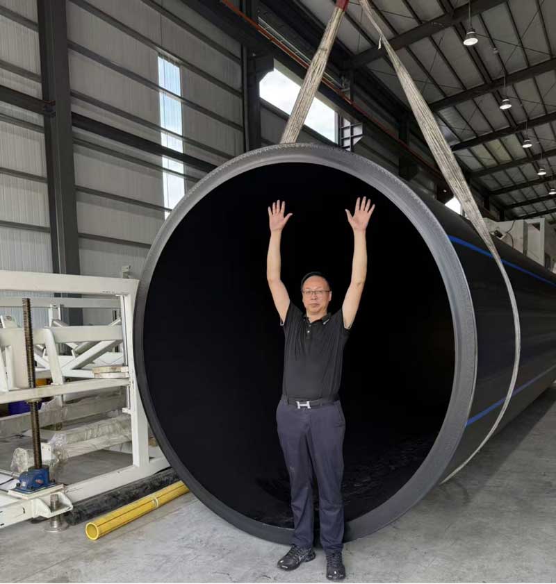
Given the large water transmission capacity, requirements for larger pipe diameters keep rising. They have been successfully applied and promoted in various fields including water supply and drainage, gas supply, agriculture and nuclear power.
In particular, numerous new breakthroughs have been achieved in large diameter thick wall PE pipes specially used for nuclear power in recent years, putting the industry at the forefront. How to tackle the difficulties in manufacturing large diameter pipes? What are the equipment technologies and production processes for large diameter pipe production? What are the future design trends and challenges for large diameter
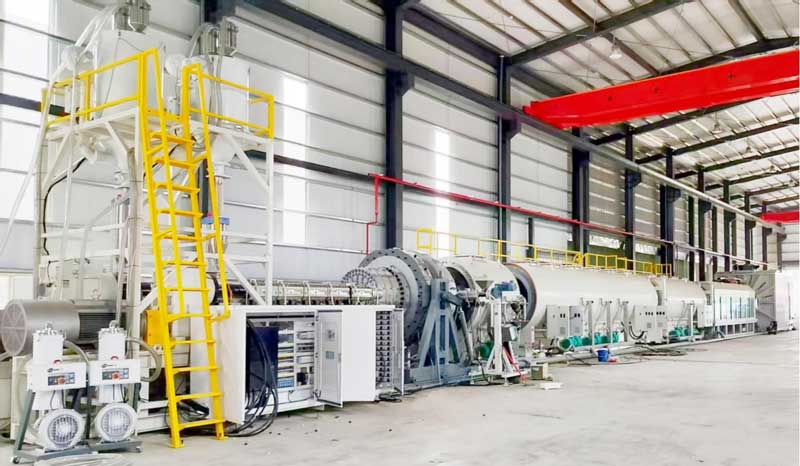
I.Equipment Configuration and Commissioning
1.Extruder Selection and Parameters
1.1 Adopt high torque single screw extruders with a length to diameter ratio of ≥40:1 and a diameter of 120 mm to ensure uniform melt plasticization and high production efficiency. Low temperature melt extrusion is achieved while guaranteeing high output and even material plasticization.
1.2 Equip an internationally branded PLC control system with temperature control precision of ±0.5 °C to avoid uneven pipe wall thickness caused by melt temperature fluctuations.
2.Die and Sizing System
2.1 The die adopts a spiral structure (alloy steel forging plus chromium plating) with zone controlled electric heating on the core for precise temperature regulation. Large volume long spiral dies are equipped with an optimized number of spiral runners as well as air cooling and oil cooling structures to further stabilize melt temperature.
2.2 Keep the distance between the sizing sleeve and the die lip short (generally ≤5 cm), and ensure balanced water pressure in the vacuum sizing tank to reduce surface ripples or grooves on pipes.
2.3 Install a melt cooling exchanger between the extruder and the die to significantly lower melt temperature, overcome sagging of HDPE raw materials, and ensure uniform pipe wall thickness. ## Invitation to the 15th Anniversary Grand Ceremony of Bohan Plastic Pipe Technology Exchange Conference
II.Pre Commissioning Preparation
1.Raw Material Pretreatment Adopt HDPE special grades of PE100 or above. When mixing with color masterbatch, dry the mixture to a moisture content of ≤0.01% to prevent melt bubbles or degradation, e.g., grade JHMGC100LST.
2.Equipment Preheating and Commissioning
2.1 Carry out staged heating for the die head: preheat for 5–6 hours at 220 °C for initial startup, and 4–5 hours for die replacement to ensure even heating of the die.
2.2 After installing the sizing water jacket, adjust its levelness and clearance with a feeler gauge (tolerance ≤0.2 mm) to prevent pipe eccentricity or uneven wall thickness.
III.Process Parameter Control
1.Temperature and Pressure
1.1 Set temperatures for each extruder zone according to the melt flow index of raw materials: Zone 1 at 160–170 °C, Zone 2 at 180–190 °C, die head zone at 200–210 °C, and keep melt pressure stable at 15–25 MPa.
1.2 Excessively high core die temperature (>220 °C) leads to rough inner walls, which requires precise regulation via a heat conducting oil circulation system.
2.Cooling and Traction
2.1 Control water temperature of the vacuum sizing tank at 10–20 °C, and apply staged cooling in the spray cooling tank (temperature difference ≤10 °C) to avoid stress cracking caused by rapid cooling.
2.2 Synchronize the tractor speed with the extrusion speed (tolerance ≤0.5%), with crawler traction force ≥5 tons to ensure uniform pipe drawing.
IV.Quality Control and Troubleshooting
1.Solutions to Surface Defects
1.1 Rough surface: Check for blocked water channels or uneven water pressure in the sizing sleeve, clean nozzles and adjust flow rates to achieve balance.
1.2 Grooves/ripples: Clean impurities on the die lip, adjust negative pressure of the vacuum sizing tank to −0.05~−0.08 MPa, and replace filter screens if necessary.
2.Dimensional Precision Assurance Inspect pipe outer diameter (tolerance ±0.5%) and wall thickness (tolerance ±5%) every 30 minutes. Adjust die clearance or traction speed when exceeding standards.
3.Solutions to Uneven Thickness, Sagging and Ovality
3.1 Uneven Thickness
3.1.1 Die Calibration and Adjustment
A.Ensure perfect alignment between the die lip and mandrel during die installation. Fasten bolts clockwise step by step then loosen them by one turn to avoid eccentricity induced by local stress.
B.Adjust wall thickness regulating bolts around the die, and mark directions on the outer pipe wall with an oil based pen after each adjustment for quick positioning of deviation areas. C. Regularly clean burnt materials within 0.5–1 cm of the die lip to prevent impurities from disturbing melt flow.
3.1.2 Process Parameter Optimization
A. Maintain extruder melt pressure at 15–25 MPa and synchronize traction speed with extrusion rate (tolerance ≤0.5%) to avoid wall thickness variations from periodic fluctuations.
B. Adjust the distance between the sizing sleeve and die lip to ≤5 cm, and balance nozzle angles and water outlet pressure of the spray cooling tank to ensure uniform cooling.
3.1.3 Real Time Detection and Correction
A.Cut samples in front of the cooling water tank, conduct multi point detection (e.g., 8 point method) with a bench drill, and adjust die clearance using a vernier caliper.
B.Integrate a laser diameter gauge for real time outer diameter monitoring, and link it with an automatic feedback system to correct traction speed or die opening/closing range.
3.2 Sagging (Melt Sagging)
3.2.1 Temperature and Cooling Control
A. Lower melt temperature by 10–15 °C compared with conventional processes, and stabilize core die temperature at ≤220 °C via a heat conducting oil circulation system.
B. Control temperature difference of the spray cooling tank in sections (≤10 °C), and raise negative pressure of the vacuum sizing tank to −0.05~−0.08 MPa to accelerate melt solidification.
3.2.2 Equipment and Process Improvement
A.Adopt spiral split flow dies with optimized runner design to enhance melt support and avoid local collapse.
B.Adjust water outlet pressure of the sizing sleeve (tolerance ≤5%), lower traction speed to below 50% of the rated value, and extend cooling time.
3.3 Ovality
3.3.1 Gravity Compensation and Sizing Optimization
A.Install multi point correction rollers (one set every 2 meters), and balance pipe stress via hydraulically regulated roller pressure.
B.Adjust water outlet pressure of the sizing sleeve (tolerance ≤5%), combined with uniform adsorption of the vacuum sizing tank to ensure roundness.
3.3.2Process Parameter Adjustment
A.Apply zone heating to the core die (tolerance ±2 °C) to prevent ovality caused by uneven melt shrinkage.
B. Inspect and clean impurities on the sizing sleeve, support plates or sealing rings to avoid deformation induced by uneven local resistance.
Recent News
12 6 月, 2026
3 4 月, 2026
10 4 月, 2025